- 您现在的位置:买卖IC网 > Sheet目录496 > OP955 (TT Electronics/Optek Technology)PHOTOTRANS SILICON PIN SIDE LOOK
Type OP955
Electrical Characteristics (T A = 25 o C unless otherwise noted)
SYMBOL
PARAMETER
MIN TYP MAX UNITS
TEST CONDITIONS
I L
I D
Reverse Light Current
Reverse Dark Current
8
1
18
60
μ A
nA
V R = 5 V, E e = 1 mW/cm 2(3)
V R = 30 V, E e = 0
V (BR)
V F
C T
t r , t f
Reverse Breakdown Voltage
Forward Voltage
Total Capacitance
Rise Time, Fall Time
60
4
5
1.2
V
V
pF
ns
I R = 100 μ A
I F = 1 mA
V R = 20 V, E e = 0, f = 1.0 MHz
V R = 20 V, λ = 850 nm, R L = 50 ?
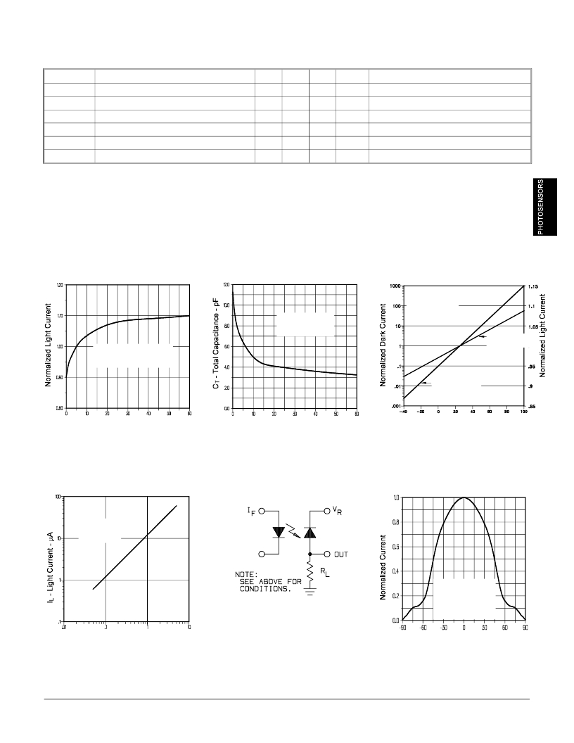
Typical Performance Curves
Normalized Light Current vs
Reverse Voltage
Total Capacitance vs
Reverse Voltage
T A = 25 o C
E e = 0 mW/cm 2
f = 1 MHz
Normalized Light and Dark
Current vs Ambient Temperature
V R = 5 V
λ = 935 nm
Normalized to
T A = 25 o C
Light Current
T A = 25 o C
λ = 935 nm
Normalized to V R = 5 V
Dark Current
V R - Reverse Voltage - V
Light Current vs. Irradiance
V R - Reverse Voltage - V
Switching Time Test Circuit
T A - Ambient Temperature - o C
Light Current vs. Angular
Displacement
V R = 5 V
T A = 25 o C
λ = 935 nm
Test Conditions:
λ = 935 nm
V R = 5 V
Distance Lens to
Lens = 1.5 inches
E e - Irradiance - mW/cm 2
θ - Angular Displacement - Deg.
Optek reserves the right to make changes at any time in order to improve design and to supply the best product possible.
Optek Technology, Inc. 1215 W. Crosby Road Carrollton, Texas 75006
3-63
(972)323-2200
Fax (972)323-2396
发布紧急采购,3分钟左右您将得到回复。
相关PDF资料
OP993
PHOTODIODE SILICON PIN TO-18
OP999
PHOTODIODE 5MM PIN 890NM
OPA729W
LED WHITE 10/1WATT 6500K ARRAY
OPA730WD
LED WHITE 12/1WATT 6500K ARRAY
OPA733WD
LED WHITE 1 WATT 6500K ARRAY
OPA739WD
LED WHITE 3/1WATT 6500K ARRAY
OPA740W23
LED WHITE 10/1WATT 6500K ARRAY
OPA741W23
LED WHITE 12/1WATT 6500K ARRAY
相关代理商/技术参数
OP-96656
制造商:Keyence 功能描述:
OP97
制造商:AD 制造商全称:Analog Devices 功能描述:Low-Power, High-Precision Operational Amplifier
OP-97
制造商:AD 制造商全称:Analog Devices 功能描述:LOW POWER, HIGH PRECISION OPERATIONAL AMPLIFIER
OP97_07
制造商:AD 制造商全称:Analog Devices 功能描述:Low Power, High Precision Operational Amplifier
OP97AJ
制造商:AD 制造商全称:Analog Devices 功能描述:LOW POWER, HIGH PRECISION OPERATIONAL AMPLIFIER
OP97AJ/883
制造商:未知厂家 制造商全称:未知厂家 功能描述:Voltage-Feedback Operational Amplifier
OP97ARC/883
制造商:AD 制造商全称:Analog Devices 功能描述:Low-Power, High-Precision Operational Amplifier
OP97AZ
制造商:AD 制造商全称:Analog Devices 功能描述:Low-Power, High-Precision Operational Amplifier
